Ever wonder how responsive your arcade stick or controller truly is? Input latency can vary between different PCBs and connection types, affecting your gameplay subtly. In the world of fighting games, a few milliseconds can make the difference in pulling off a combo. This guide will show you how to build a basic Arduino-powered input lag tester at home.
Using a simple circuit and code, you can measure the time delay between a button press and the signal registering on your controller’s output. We’ll provide a parts list, a circuit diagram, sample Arduino code, and instructions on testing and interpreting results. Even if you’re a beginner with electronics, fear not, this is a hobbyist-friendly project.
By the end, you’ll be able to quantify your stick’s latency (in milliseconds), know what’s “good” or “bad” lag, and understand why and when to perform such tests (for example, after mods or when comparing wired vs wireless modes).
How Does It Work?
The core idea is to use an Arduino as a tiny input measurement device. We will have the Arduino simulate a button press on your fight stick’s PCB by sending an electrical signal, and simultaneously the Arduino (with a USB host shield) will listen for the controller’s input report that the button was pressed. By comparing the two, we get the lag. Essentially:
- The Arduino sets a particular pin HIGH to short your stick’s button input (tricking the PCB into thinking the button was pressed).
- The Arduino, acting as a USB host to the controller, detects when the controller’s state changes to “button pressed.”
- The time difference between sending the signal and the controller’s report is measured.
This method isolates the controller/stick’s PCB latency (the time it takes for the stick’s electronics to register and report a press). It doesn’t include TV/monitor display lag or game engine lag – it’s purely the controller’s contribution. That makes it a very direct measurement of your hardware’s performance.
Parts and Tools Needed
- Arduino Uno or Mega – A standard Arduino with an SPI interface for the host shield. (Other Arduino models can work too, but Uno is common.)
- USB Host Shield for Arduino – This is an add-on board that lets the Arduino act as a USB host (so it can communicate with your fight stick as a USB device). Make sure it’s one compatible with the Arduino model you use.
- Wires – A few jumper wires to make connections. Preferably at least one with an alligator clip or a Dupont jumper that can attach to your fight stick’s button input.
- 1N4148 Diode (or similar) – A small signal diode used to protect your controller’s circuit when injecting the signal. This ensures current only flows in safe ways when the Arduino triggers the button.
- Breadboard or solder (optional) – You can use a small breadboard to set up the diode and connections, or directly solder wires and the diode inline if you prefer a permanent tester.
- Computer with Arduino IDE – To program the Arduino and view results (serial monitor).
Circuit Diagram Overview: We will connect an Arduino output pin (digital pin 7 in our example) to the fight stick’s button signal line through a diode. The other side of that button on the fight stick should be common ground (most arcade PCBs use a common ground, which we assume here). The USB host shield will be mounted on the Arduino, and you’ll plug your controller into the host shield’s USB port.
For clarity, here’s a simplified wiring scheme:
- Arduino digital pin 7 -> diode (direction from Arduino to controller input) -> controller’s button signal.
- Controller ground -> Arduino GND (common ground reference).
- The USB connection from the controller goes into the host shield on the Arduino.
This setup allows the Arduino to “press” the button electrically by driving pin 7 HIGH (5V) which, via the diode, will activate the button input on the controller PCB. The diode prevents the controller’s own signals from feeding back into the Arduino output.
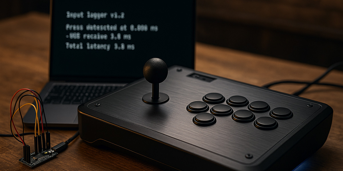
Below is an example diagram of the hardware setup:
Hardware setup for input lag testing: an Arduino with USB host shield (left) connected to a fight stick’s button wiring (right). The diode on the line ensures the Arduino’s simulated press doesn’t back-feed into the controller circuitry.
Arduino Code Sample
We’ll use an existing open-source Arduino sketch from the input lag testing community as a starting point. The code configures the Arduino’s USB Host to communicate with the controller and sets up pin 7 as our trigger. Below is a simplified pseudo-code illustrating the core logic:
cppCopy#include <USBHost.h>      // Pseudocode: include a USB Host library
// ... (plus libraries for HID if needed)

const uint8_t BUTTON_PIN = 7;
USBHost usb;
GamepadController controller(&usb);  // assume an interface to the controller

void setup() {
  Serial.begin(115200);
  pinMode(BUTTON_PIN, OUTPUT);
  digitalWrite(BUTTON_PIN, LOW);         // start with button not pressed
  usb.Init();
  // Wait for controller to attach
  while (!controller.connected()) {
    usb.Task();
  }
  Serial.println("Controller connected. Ready.");
}

void loop() {
  // Example: trigger a test on command
  if (Serial.read() == 't') {            // send 't' from serial to start test
    // 1. Press the button via Arduino
    digitalWrite(BUTTON_PIN, HIGH);
    unsigned long t_start = micros();
    // 2. Wait for controller to report button pressed
    while (!controller.getButtonState(BUTTON_INDEX)) {
      usb.Task();  // process USB tasks
    }
    unsigned long t_end = micros();
    digitalWrite(BUTTON_PIN, LOW);       // release button
    unsigned long latency_us = t_end - t_start;
    Serial.print("Lag: ");
    Serial.print(latency_us / 1000.0, 3);
    Serial.println(" ms");
  }
}
In practice, you might not write this from scratch – the community has provided programs (for example, the inputlag.science lag tester program on GitLab) that you can directly use. The gist of the code is:
- Set up the USB host and wait for the controller to be recognized.
- On a trigger (could be a serial command or a loop), set the Arduino output HIGH to simulate the button press.
- Record the time (
t_start) immediately when pressing. - Continuously poll the controller’s state via the USB host library until the button press is detected in the controller’s report.
- Record the time (
t_end) when it’s detected, then compute the difference. - Print the result.
This will give you the latency in microseconds (we convert to milliseconds for readability). You may run multiple trials and average them for accuracy.
Running the Test
- Wire up the circuit: Connect the Arduino pin 7 to your chosen button’s signal line on the controller PCB through the diode. A convenient place is often on the button’s microswitch solder joint or a pin on the PCB. Connect grounds together. Double-check the diode orientation (band towards the controller side usually).
- Upload the code to the Arduino using the Arduino IDE. Ensure you have any required USB host libraries installed.
- Open the Serial Monitor in Arduino IDE at 115200 baud (as set in code).
- Plug your controller into the Arduino’s USB host port. The serial output should indicate the controller is connected. (If nothing happens, the controller might not be recognized – you may need to add specific USB HID descriptors in code for your controller PCB. Most generic XInput/DInput devices will be recognized by common libraries.)
- Initiate a test: For the provided pseudo-code, you’d send the character
tin the Serial Monitor to start a trial. The Arduino will then toggle the button and measure the time. - View results: The Serial Monitor will output a latency measurement for each test, e.g., “Lag: 4.167 ms”. It’s wise to run many trials (dozens or more) to account for variability. Some tools automate this by looping and then calculating stats like average and standard deviation.
- Multiple button tests (optional): If you want to test different buttons or directions, you can move the wire to another input on the PCB. The latency usually doesn’t differ much between buttons on the same PCB, but for thoroughness you might try a stick direction vs a button to see if any difference exists.
Interpreting the Results
You’ll get a series of time measurements in milliseconds. Here’s how to make sense of them:
- Average latency: This is the primary number – how long on average between the physical activation and the reported activation. For example, a Brook Universal Fighting Board might show ~1.0 ms average, whereas a generic gamepad PCB could be ~4–5 ms.
- Consistency (% on time): Some measurements, like those from inputlag.science, use a “% on time” which indicates how often the controller reports on the very next possible USB poll. But if you’re doing simple at-home tests, you might just focus on milliseconds.
- Typical values:
- Under 1ms: Exceptional. Very few controllers achieve this consistently, but some DIY boards with high polling rates or certain firmware can get close to 0.7ms. This is essentially negligible lag.
- ~1–4ms: Excellent. Most top-tier fight stick PCBs (e.g., Brook UFB series, high-end console pads) fall in this range. For reference, 16.7ms is one frame at 60Hz, so 4ms is only ~1/4 of a frame – virtually imperceptible.
- ~5–10ms: Good/Moderate. Many official controllers (especially wireless ones) might be in this ballpark. For example, a DualShock 4 over Bluetooth averages ~3ms (surprisingly low due to high poll rate), while some third-party controllers or older PCB designs might be 6–8ms.
- Above 10ms: Laggy. If you see averages like 15ms or more, that’s nearly a full frame or more of delay. Some older arcade sticks (e.g., early PS3-era boards) and certain encoder boards have been measured in the ~15–20ms range. For instance, the first firmware of the Nacon Daija reportedly had ~17ms average latency – a figure so high that a firmware update later improved it to ~4ms. Consistently high values might be noticeable in gameplay as a slight “sluggishness.”
To put it in perspective, anything under ~5ms is excellent for controller latency, 5–10ms is usually fine (you likely won’t feel it unless you’re very sensitive or comparing side-by-side), and >10ms might be a disadvantage in competitive play. In real terms, blinking your eye takes about 100-150ms, so a few milliseconds is tiny – but in a tight match, every millisecond counts.
Sometimes you’ll also observe outlier values. USB polling intervals can cause quantization of results. For example, if a device polls at 4ms intervals, you might see measurements clustering around 4ms, 8ms, etc., depending on when the press falls relative to the poll cycle. That’s normal. Modern boards often use 1ms polls (1000 Hz) for minimal delay.
For a concise summary, here’s a small table of example results from known tests:
| Controller/PCB | Avg Lag (ms) | Notes |
|---|---|---|
| Brook UFB (wired, PS4 mode) | ~1.0 ms | Top-tier aftermarket PCB (very consistent). |
| Brook UFB-Fusion (PS5 mode) | ~0.8 ms | One of the best, essentially ~0.8ms. |
| Sony DualShock 4 (Bluetooth) | ~3.0 ms | Surprisingly low due to high poll rate (wireless). |
| Hori Fighting Commander (wired) | ~3.4–3.8 ms | Good for an official pad controller. |
| Original Nacon Daija (pre-patch) | ~17.0 ms | Very high initially – improved with firmware update. |
| Generic USB encoder board (Xin-Mo) | ~4.2 ms | Typical inexpensive encoder latency. |
Table: Sample input latency averages for various controllers from test data.
Why and When Should You Test Latency?
- After Modding or Custom PCB Install: If you’ve just installed a new PCB in your stick (e.g., Brook board, Arduino-based GP2040 board, etc.), it’s a great idea to test the latency. Most reputable boards publish their expected latency, but verifying ensures everything is working right. For instance, if you accidentally set a PCB to a slower polling mode, a test would reveal that.
- Comparing Wired vs Wireless: Some sticks, like the Mayflash F700, have Bluetooth functionality. You can measure lag in wired mode versus wireless. Often, wired will be slightly faster and more consistent. If wireless shows, say, 2ms more on average, you might decide if the convenience is worth the trade-off.
- Periodic Performance Checks: Over time or after firmware updates, you might re-test to ensure no regressions. Most of the time hardware doesn’t “slow down” on its own, but this can be a fun periodic calibration.
- Satisfying Curiosity and Community Sharing: It’s just interesting to know where your device stands. The fighting game community loves sharing this info on forums like r/fightsticks. By testing your stick, you can contribute data – especially if you have an uncommon controller to benchmark.
- Diagnosing Perceived Lag: If you feel your inputs are delayed, a lag test can either confirm it or give peace of mind. Sometimes the culprit is actually elsewhere (monitor lag, game frame rate, etc.), but testing the controller removes one variable.
Tips for Accurate Testing
- Use a High Frame Rate Camera (alternative method): If the Arduino method is daunting, a simpler (though less precise) method is the high-speed camera test. For example, wire an LED to your button signal (LED lights when you press the button), record a gameplay footage at 240fps, and count frames between button light and character action. This gives a rough total lag (including game and display). But the Arduino method we’re doing is more direct for PCB lag specifically.
- Multiple Trials: Don’t rely on a single press. Do dozens or hundreds and calculate the average. The Arduino can even automate this by looping the test (
forloop) and then printing an average at the end. - Ensure Common Ground: The method assumes your stick’s PCB uses a common ground for inputs (almost all do). If by chance it doesn’t, you’d need a slightly different approach (like using an optocoupler or a transistor to simulate the button press).
- Don’t Mix Up ms and μs: 5000 microseconds is 5 milliseconds. Be careful when reading Arduino
micros()output. - Polling Rate Consideration: Some advanced testers will even try forcing different polling rates (e.g., 1ms vs 4ms) to see how the device behaves. Our basic approach will just use the device’s native polling. The results will inherently reflect that.
Performing an input lag test with an Arduino gives you concrete insight into your controller’s performance. You now have a way to quantify that responsiveness: whether your custom stick truly is “fast” or if a fancy wireless pad is introducing a few extra milliseconds. The good news is that most modern fight stick PCB’s are extremely quick – often only 1–4ms delay, which is practically tournament-grade. If you do find a laggy board (10ms+), you might consider an upgrade if competitive play is your goal.
Regular testing isn’t necessary for everyone, but it’s an eye-opening project for tech-minded gamers. It blends the worlds of DIY electronics and gaming in a useful way. And as the fighting game community says: “Frame data matters” – now you’ve taken that to the hardware level!
Happy testing, and may your reactions be as fast as your controller! If you found high latency, don’t despair – use this info to make improvements (maybe it’s as simple as switching to a wired connection or updating firmware). With knowledge in hand, you can ensure nothing in your setup is holding you back from hitting those one-frame links.
Sources
- Controller Lag Methodology, inputlag.science
- Controller Lag Results, inputlag.science
- How to test input lag / delay of fight stick on pc?, /r/figthsticks, reddit.com
- What is the best option for a low latency arcade stick?, misterfpga.org
- MiSTer Input Latency micro update, @MisterAddons, X.com


